To Place the Steel Columns
-
Select
 (
Steel Column ) from the
ribbon.
(
Steel Column ) from the
ribbon.
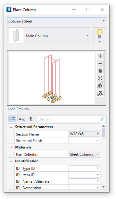
The Place Column tool settings window opens so you can change placement settings, Structural member data, etc.
Your pointer changes from the standard crosshair to a crosshair combined with the shape of a steel column, attached at the column’s base. - Select the Main Column instance type. Then select a section size of W8X31 and enter a Length of 12:0. We will also use the defaults for all the settings for coping and all the settings on the Properties and Analytical tabs.
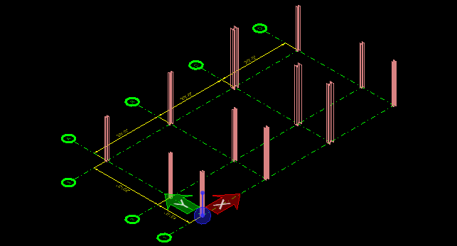
- Maximize window 2, the isometric view. Place your mouse pointer at the intersection of the grid lines labeled A and 1 (top left). As you move your pointer around the grid you will notice the AccuSnaps targets highlight as you near grid locations.
-
Look down at the status bar. This line regularly displays prompts
telling you what your next step is to achieve the desired outcome for the
currently selected tool. Now it says Enter data point to place member, so
place your pointer at the A1 intersection where the gridpoint snaps target
highlights, and enter a data point (click your left mouse button) to place the
column. Continue placing columns at B1, C1, A4, B4, and C4, using the
highlighted targets on the grid as your guide.
Your first six columns are placed. You still have the Place Steel Column - Primary tool actively selected, so your pointer is still attached to a column shape.
- Because our structure is cantilevered, the next columns must be of different length from the first ones. In the Place Steel Column – Primary tool settings window, select a section size of W10X45 and enter a Length of 14:0.
- Press <Enter>, then place three columns at the A2, B2, and C2 intersections. View 2 should now look like the figure below.
-
Finally, we need to place the last set of columns. In the Place
Steel Column — Primary tool settings, select a section size of W14X90 and enter
a Length of 16:0.
Tip: If the section W14X90 does not appear in the section Name drop list, click the value field to browse for W14X90 in a section picker. Once selected, it will appear in the Place Steel Column – Primary tool settings.
- Press <Enter>, then place three columns at the A3, B3, and C3 intersections. View 2 should now look like the figure below.
-
Click
Commit Changes to commit your changes to
design history
The Commit changes text box appears. Enter your changes and click OK.